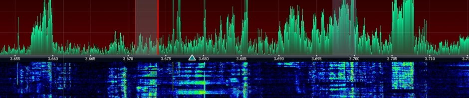
The QRM Eliminator is inserted into the feedline from the trx to the antenna without any additional modifications required to the radio. The box has a built-in PTT control which enables the Eliminator to stay connected during transmit. An additional auxiliary receiving antenna is required, though, like a 2m antenna or simply a couple of meters wire in the shack. The unwanted signal is received with both antennas, resulting in different phases. The QRM Eliminator now allows adjusting the phase angle as well as amplification in a way to cancel out the unwanted signal before it reaches the receiver front end! It’s based on a totally innovative concept and cannot be compared to the normal ‘noise blanker’ performance.
X-Phase is located in a shack in the vicinity of your TRX and is included in the gap of the antenna feeder. In case you are using PA, between TRX and PA. Thus, the “Main” jack must be connected main operating antenna or PA input. Connect the “TRX” jack to the antenna socket of the transceiver. To the “AUX” jack, connect the AUX antenna, 2 to 5 meters of any wire stretched along the shelf of your shack. The QRM Eliminator contains interface circuitry necessary for operation with most modern HF transceivers.
As can be seen from the circuit diagram, the X-Phase device in transmission mode forms through high-frequency channel between the connectors “TRX” and “MAIN”. Maximum The power of the high-frequency signal transmitted through this channel should not be exceeded 100 watts! Do not connect the instrument to the PA output under any circumstances!
Can be used with civilian radio stations. (CB 27 mHz)
Instruction here
Soldering manual here
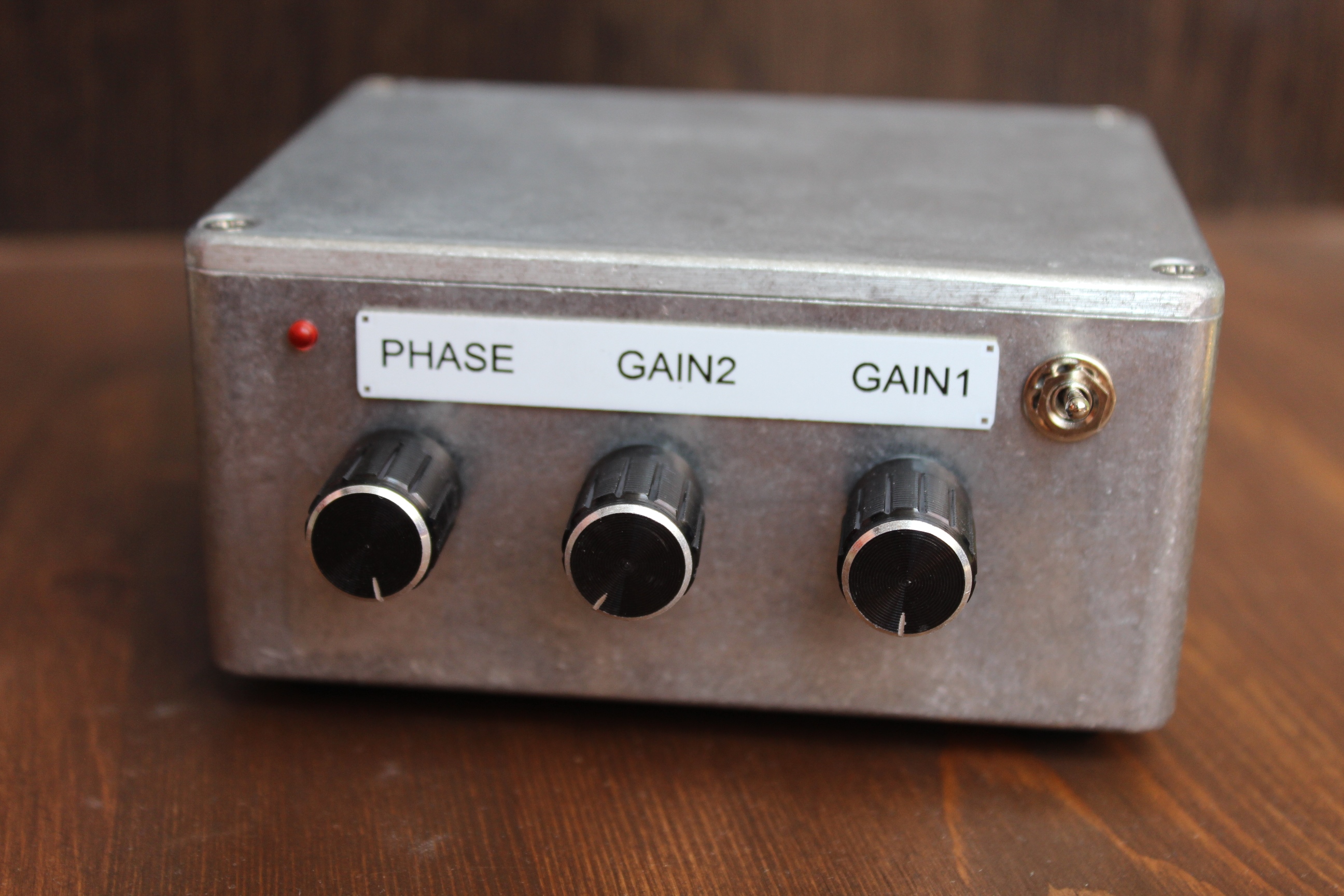
Aluminum enclosure, full assembled.
Dimension 114*89*55 mm
Weight: 400g
Cost: 65USD
DIY KIT (all parts + PCB, without enclosure and connectors)
Weight: 90g
Cost: 32USD